[ITEM] [/ITEM]
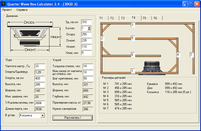
Quarter Wave Box Calculator 7,9/10 5285 votes
Mar 15, 2016 - Of course, you can model the dimensions and internals of the box, but the problem. Transmission line just takes the back waves generated from the speaker. Find the length of the transmission line by dividing that wavelength by 4 (the quarter wavelength). Speaker lobing calculator – Polar response. Quarter Wave Flared Vent T-Line Horn Bass Reflex Enclosure Calculator.
What is a transmission line speaker? Also called acoustic labyrinth or maze, the transmission line speaker design is a type of enclosure that follows a simple concept, yet hard to achieve. The design is pretty straight forward, but the hard part is that there is no reliable software to model the enclosure results in an accurate fashion. Of course, you can model the dimensions and internals of the box, but the problem is the damping material. The transmission line speaker design relies on heavy use of dampening material.
The different types of material used, the amount, the thickness, the location where it is placed, all contribute to a different end result. That’s why it is very hard to predict the result with a transmission line. The ways you can place damping material inside the enclosure are practically endless. How you do so, will dictate whether the enclosure will sound good or bad.
Trial and error is key to making a good transmission line. This makes it difficult for a mass producer (which is the reason why you rarely see transmission lines in your local audio store), but some DIY-ers love to tinker, and the fact that the transmission line speaker design is difficult and time consuming, will only attract them even more. How does a transmission line speaker design work? Transmission lines (TL for short) work a bit differently, compared to sealed and ported boxes. When you make a sealed or bass reflex enclosure (passive radiator slips into this category as well), you alter the resonant peak of the speaker. Transmission line just takes the back waves generated from the speaker, inverts their phase, and throws them back in front of the speaker, to combine with the front waves. This is the main principle around how the transmission line works.
You have to understand that this is just the concept behind how the transmission line is designed. You will soon discover, that TL has some serious problems with resonant modes, which need adequate damping. Here is how to design the transmission line: • Take your speaker and find out what is the resonant frequency in free air (F s). • Find the corresponding wavelength for that F s. • Find the length of the transmission line by dividing that wavelength by 4 (the quarter wavelength).
• Make a path from the back of the speaker to the front of the speaker, which is exactly the length you just calculated. • The path can take different shapes.
A labyrinth is popular because it saves spaces (so enclosure doesn’t get enormous). • Damp the path with different materials of various thicknesses. • The damping material will absorb the upper frequencies, which introduce some resonance problems. • If the upper frequencies are successfully absorbed, all that is left is the low frequencies from the back of the speaker, which will combine with those in the front. These are the general milestones you need to go through, when you are designing and building your transmission line enclosure. Of course, there are other things to worry about, but let’s just keep it simple for now, so you can get the main idea on how the transmission line speaker design works. What shape should the line be?
Various shapes are available for you to choose. Using different techniques will yield different results, but sometimes the physical aspect is just plain ugly.
Most of the time, you cannot turn a blind eye to this issue. One of the first, featured a pipe to guide the back waves. The length of the pipe was 25% of the wavelength of the resonant frequency (F s) of the speaker. The diameter of the pipe was in correlation with the diameter of the speaker. To be more exact, the cross section of the pipe was equal to the S d (cone area + half of surround) of the speaker. I know this is hard to imagine, because you probably never seen such intricate design. No boxes, no baffles, just a pipe which is attached to the back of the speaker, at one end, and the other end pointing in the same direction as the front of the speaker.
• Windows XP: Click the Remove or Change/Remove tab (to the right of the program). • Windows XP: Click Add or Remove Programs. Or, you can uninstall eBike Diagnostic Software from your computer by using the Add/Remove Program feature in the Window's Control Panel. • On the Start menu (for Windows 8, right-click the screen's bottom-left corner), click Control Panel, and then, under Programs, do one of the following: • Windows Vista/7/8: Click Uninstall a Program. • When you find the program eBike Diagnostic Software, click it, and then do one of the following: • Windows Vista/7/8: Click Uninstall. 
- Author: admin
- Category: Category
Search
Blog
- Prikaz O Naznachenii Glavnogo Inzhenera Proekta Obrazec
- Drajvera K Trust Primo Webcam
- L293d Motor Driver Circuit Diagram Pdf
- Ice Cube Gangsta Rap Made Me Do It Wiki
- Ww Greener Shotguns Serial Numbers
- Anime Bakugan Battle Brawlers Sub Indo Full Episode
- Kommercheskoe Predlozhenie Na Postavku Myasa Obrazec
- Plagin Nozhi Dlya Ks 16 Dlya Deathrun Serp
- Railclone Pro Keygen
- Baylis Smith And Owens The Globalization Of World Politics Pdf
- Zvuk Trojka S Bubencami
- Bmw Dvd Unlock Software Free
- Reshebnik Fly High Activity Book 3
Quarter Wave Box Calculator 7,9/10 5285 votes
Mar 15, 2016 - Of course, you can model the dimensions and internals of the box, but the problem. Transmission line just takes the back waves generated from the speaker. Find the length of the transmission line by dividing that wavelength by 4 (the quarter wavelength). Speaker lobing calculator – Polar response. Quarter Wave Flared Vent T-Line Horn Bass Reflex Enclosure Calculator.
What is a transmission line speaker? Also called acoustic labyrinth or maze, the transmission line speaker design is a type of enclosure that follows a simple concept, yet hard to achieve. The design is pretty straight forward, but the hard part is that there is no reliable software to model the enclosure results in an accurate fashion. Of course, you can model the dimensions and internals of the box, but the problem is the damping material. The transmission line speaker design relies on heavy use of dampening material.
The different types of material used, the amount, the thickness, the location where it is placed, all contribute to a different end result. That’s why it is very hard to predict the result with a transmission line. The ways you can place damping material inside the enclosure are practically endless. How you do so, will dictate whether the enclosure will sound good or bad.
Trial and error is key to making a good transmission line. This makes it difficult for a mass producer (which is the reason why you rarely see transmission lines in your local audio store), but some DIY-ers love to tinker, and the fact that the transmission line speaker design is difficult and time consuming, will only attract them even more. How does a transmission line speaker design work? Transmission lines (TL for short) work a bit differently, compared to sealed and ported boxes. When you make a sealed or bass reflex enclosure (passive radiator slips into this category as well), you alter the resonant peak of the speaker. Transmission line just takes the back waves generated from the speaker, inverts their phase, and throws them back in front of the speaker, to combine with the front waves. This is the main principle around how the transmission line works.
You have to understand that this is just the concept behind how the transmission line is designed. You will soon discover, that TL has some serious problems with resonant modes, which need adequate damping. Here is how to design the transmission line: • Take your speaker and find out what is the resonant frequency in free air (F s). • Find the corresponding wavelength for that F s. • Find the length of the transmission line by dividing that wavelength by 4 (the quarter wavelength).
• Make a path from the back of the speaker to the front of the speaker, which is exactly the length you just calculated. • The path can take different shapes.
A labyrinth is popular because it saves spaces (so enclosure doesn’t get enormous). • Damp the path with different materials of various thicknesses. • The damping material will absorb the upper frequencies, which introduce some resonance problems. • If the upper frequencies are successfully absorbed, all that is left is the low frequencies from the back of the speaker, which will combine with those in the front. These are the general milestones you need to go through, when you are designing and building your transmission line enclosure. Of course, there are other things to worry about, but let’s just keep it simple for now, so you can get the main idea on how the transmission line speaker design works. What shape should the line be?
Various shapes are available for you to choose. Using different techniques will yield different results, but sometimes the physical aspect is just plain ugly.
Most of the time, you cannot turn a blind eye to this issue. One of the first, featured a pipe to guide the back waves. The length of the pipe was 25% of the wavelength of the resonant frequency (F s) of the speaker. The diameter of the pipe was in correlation with the diameter of the speaker. To be more exact, the cross section of the pipe was equal to the S d (cone area + half of surround) of the speaker. I know this is hard to imagine, because you probably never seen such intricate design. No boxes, no baffles, just a pipe which is attached to the back of the speaker, at one end, and the other end pointing in the same direction as the front of the speaker.
• Windows XP: Click the Remove or Change/Remove tab (to the right of the program). • Windows XP: Click Add or Remove Programs. Or, you can uninstall eBike Diagnostic Software from your computer by using the Add/Remove Program feature in the Window's Control Panel. • On the Start menu (for Windows 8, right-click the screen's bottom-left corner), click Control Panel, and then, under Programs, do one of the following: • Windows Vista/7/8: Click Uninstall a Program. • When you find the program eBike Diagnostic Software, click it, and then do one of the following: • Windows Vista/7/8: Click Uninstall.
Search
Blog
- Prikaz O Naznachenii Glavnogo Inzhenera Proekta Obrazec
- Drajvera K Trust Primo Webcam
- L293d Motor Driver Circuit Diagram Pdf
- Ice Cube Gangsta Rap Made Me Do It Wiki
- Ww Greener Shotguns Serial Numbers
- Anime Bakugan Battle Brawlers Sub Indo Full Episode
- Kommercheskoe Predlozhenie Na Postavku Myasa Obrazec
- Plagin Nozhi Dlya Ks 16 Dlya Deathrun Serp
- Railclone Pro Keygen
- Baylis Smith And Owens The Globalization Of World Politics Pdf
- Zvuk Trojka S Bubencami
- Bmw Dvd Unlock Software Free
- Reshebnik Fly High Activity Book 3